Protective-system documents only protect a crew when field conditions match the written limits and someone with authority checks that match before entry. A trench box, hydraulic shore, sloped cut, or engineered support plan can look substantial while still being used outside the assumptions that made the system acceptable. The practical question is not whether a drawing exists. It is whether the employer, supervisor, and competent person can connect the exact system in the ground to the exact written information that governs it.
That connection becomes especially important when the trench deepens, soil changes, water appears, surcharge loads move closer, a shield is stacked, or a crew alters the installation sequence. OSHA's excavation requirements allow several design paths for protective systems, including options based on the standard's appendices, manufacturer's tabulated data, other tabulated data approved by a registered professional engineer, and project-specific engineering. Each path comes with conditions and documentation that must be understood and followed. A generic brochure, an unreadable photograph of a chart, or data for a similar model is not a reliable substitute for the controlling information.
This article focuses on the handoff between protective-system design information and daily field decisions. It does not replace a project-specific design, manufacturer instructions, or advice from a registered professional engineer. It gives employers and competent persons a framework for checking identity, limits, configuration, loads, installation, and changes before employees depend on the system.
Why Design Data at the Trench Matters
OSHA Subpart P requires employees in excavations to be protected from cave-ins by an adequate protective system unless a stated exception applies. The system must resist without failure the loads that are intended or could reasonably be expected. Those requirements make protective-system selection a field control issue, not a paperwork exercise. A shield rated for one depth or soil condition does not automatically remain suitable when the excavation becomes deeper, wetter, more heavily loaded, or differently configured.
Tabulated data translate engineering assumptions into usable limits. Depending on the system, the data may address maximum depth, allowable spacing, member sizes, cylinder extension, stacking, allowable excavation below the system, soil classifications, surcharge loads, and installation details. Project-specific designs may add sequencing, bracing, connection, monitoring, or adjacent-structure requirements. If the crew cannot identify the applicable limits, it cannot confidently tell whether the installed system remains within them.
Document control also matters because protective systems are assembled from physical components that can be mixed up. A yard may contain several shield models with similar colors, spreaders of different lengths, hydraulic shores with different capacities, and replacement parts from different product lines. The competent person should be able to match model plates, component markings, dimensions, and configuration details to the data being used. If identity cannot be established, the employer should resolve that uncertainty before entry rather than assume that similar-looking equipment has identical limits.
Field changes create another failure point. A crew may begin with a shallow cut and then chase grade. An excavator may be repositioned. Spoil, pipe, traffic, or a crane setup may introduce loads that were not present during the morning review. Rain may change soil behavior or create water pressure. A utility conflict may force a wider excavation or a different shield position. These are not minor administrative changes when they affect the conditions used to select the system.
The presence of paperwork does not transfer responsibility away from the employer. The employer must select and construct the system according to an allowed design option, keep required information at the jobsite during construction when the standard calls for it, and ensure the system is installed and used as designed. The competent person's inspections then help detect evidence of a possible cave-in, protective-system failure, hazardous atmosphere, or other hazardous condition. When such evidence is found, exposed employees must be removed until necessary precautions have been taken.
What Employers and Supervisors Need to Know
The first step is to identify the design route being used. For sloping and benching, the employer may use the conservative slope option, Appendices A and B, other tabulated data, or a design approved by a registered professional engineer. For support, shield, and other protective systems, the employer may use Appendices A, C, or D where applicable, manufacturer's tabulated data, other tabulated data approved by a registered professional engineer, or a project-specific design. Mixing pieces of different routes without confirming that the result is allowed can create a configuration that no document actually covers.
Supervisors should know which document controls each part of the installation. A manufacturer's table may govern a shield body and spreader arrangement, while an engineered detail governs a special crossing, adjacent foundation, or unusual surcharge. The site package should make those relationships obvious. A simple cover sheet can list the equipment identification, controlling document title and revision, approved configuration, soil classification basis, planned depth, known loads, and the person to contact when conditions fall outside the stated limits.
Depth must be measured and compared with the data, not estimated from the operator's seat. The review should distinguish total excavation depth from any permitted distance below the bottom of a shield or support member. OSHA allows excavation below certain support systems or shields only within stated conditions, including design capacity for the full depth and no indications of possible soil loss from behind or below the system. The familiar two-foot provision is not a blanket permission to leave a void beneath every shield in every condition.
Soil information must remain connected to the selected system. A classification made before excavation can change when the cut exposes another layer, previously disturbed soil, fissures, water, or vibration effects. Appendix A requires classification by a competent person using at least one visual and one manual analysis, subject to the appendix's requirements. If the design data assume a soil type that no longer matches the exposed material, the selection should be reevaluated before work continues.
Loads deserve an explicit discussion. The system must account for loads that are intended or could reasonably be expected. That review can include spoil, stored pipe, excavator position, road traffic, lifting operations, nearby structures, vibration, water, and equipment crossing points. A table may include a standard surcharge assumption, but the crew should not guess whether the actual site falls within it. When the data do not address a load or configuration, the employer should seek the appropriate manufacturer or engineering direction.
Installation and removal sequences are part of the system. Support members should be installed and removed in a manner that protects employees from cave-ins, structural collapse, and being struck by components. OSHA requires support-system installation to be closely coordinated with trench excavation. A correct final arrangement does not make an unsafe intermediate stage acceptable. Supervisors should plan where employees and equipment will be during each step, how components will be handled, and what conditions trigger a pause.
Accessibility is more than keeping a binder in a truck. The controlling information should be legible, complete, and available to the people making decisions during the shift. Electronic copies can help, but the team needs a plan for dead batteries, weak service, and revision control. If a printed field copy becomes wet or damaged, replace it. If the manufacturer issues a newer revision, do not silently swap it into the package without confirming how it affects the installed equipment and current plan.
A Field Verification Routine Before Entry
Start with equipment identity. Record the manufacturer, model, serial or asset number when available, shield dimensions, spreader or shore type, and visible component markings. Compare those facts with the controlling data. Photographing the identification plate can support the record, but the photograph should supplement rather than replace a deliberate comparison. Missing plates, illegible markings, unauthorized repairs, bent members, damaged welds, or mismatched components require resolution before reliance on the system.
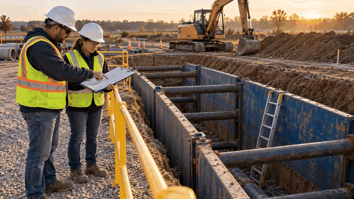
Next, verify the excavation geometry. Measure depth, width, slope or bench dimensions, shield position, and any distance excavated below the system. Check that employees will be protected while entering and leaving the protected area. Confirm that the system extends and is positioned as the design requires, that sudden lateral movement is restricted where applicable, and that no one will be inside a shield while it is installed, removed, or moved vertically.
Then compare actual conditions with the document assumptions. Confirm the competent person's soil classification, visible layering, water conditions, weather effects, nearby loads, vibration sources, and adjacent structures. Look for tension cracks, sloughing, bulging, raveling, subsidence, soil flowing from behind or beneath a system, damaged components, or shifting connections. The competent person should also inspect the adjacent area because a warning sign may develop outside the cut before it becomes obvious inside.
Review the day's work sequence. Ask whether the trench will deepen or widen, whether the shield will move, whether utilities will be crossed, whether pipe or equipment will be staged differently, and whether another contractor will introduce loads. A system that fits at the start of the shift may not fit the planned condition two hours later. Mark the hold points at which the competent person must recheck the excavation and the design data before the next phase begins.
Verify authority and communication. The competent person must have authorization to take prompt corrective measures. Crew members should know who fills that role, how to contact that person, and which changes require immediate evacuation or a pause. If a worker notices soil movement, water, a damaged component, or a change in load, the response should not depend on finding a particular form. The first action is to protect people, then document and resolve the condition.
Finally, record the decision in a concise, usable way. A field record can identify the controlling data and revision, system and component IDs, measured depth and geometry, soil classification, loads reviewed, observed conditions, deviations, corrective actions, and the competent person's name and time of inspection. OSHA Subpart P does not turn every inspection into a specific form requirement, but a consistent record can help employers communicate decisions, manage shifts, and demonstrate that changes were evaluated rather than overlooked.
Training Support for Document-to-Field Decisions
Training should teach more than the names of sloping, shoring, and shielding. Competent persons need to practice reading limits, matching components, identifying assumptions, measuring field conditions, and recognizing when a situation is outside the document. Supervisors need enough knowledge to preserve the approved plan during scheduling, equipment moves, and production changes. Crew members need to recognize warning signs and understand that stopping entry is a protective action, not a production failure.
A useful exercise begins with an actual or representative set of tabulated data and photographs of several field configurations. Learners identify which configuration is covered, which is outside the limits, and what information is missing. Scenarios can introduce changing depth, mixed soil, a longer spreader, water, a nearby excavator, or stacked shields. The goal is not to turn every learner into an engineer. It is to make the boundary between an allowed selection and an unresolved deviation visible.
Hands-on inspection practice should include equipment identification and damage recognition. Learners can locate model plates, compare component markings, measure critical dimensions, and find the document revision. They should discuss what to do when a plate is unreadable, a weld appears repaired, a pin is substituted, or a component comes from an unknown system. The expected answer should include isolating the uncertainty, preventing exposure, and obtaining qualified direction rather than improvising.
Training should also separate roles. A competent person can identify hazards and has authority to correct them, but that designation does not automatically authorize the person to redesign a protective system. A registered professional engineer has a distinct role where the standard or site conditions require engineering. Manufacturer representatives can clarify their equipment data, but field crews still need employer procedures for receiving, documenting, and implementing that direction. Clear escalation paths prevent a schedule decision from becoming an unauthorized design change.
Refresher discussions are most effective when tied to events. A new shield model, revised manufacturer data, unusual depth, adjacent foundation, heavy surcharge, damaged component, or field deviation is a reason to revisit the plan. Short pretask reviews can reinforce the controlling limits for the day's configuration. After a change, the team can review what triggered the reevaluation and how the final decision was communicated.
An excavation safety course can support the knowledge needed to recognize protective-system options, competent-person responsibilities, inspection triggers, and common trench hazards. Course completion alone does not make a person competent. The employer must evaluate the individual's knowledge, experience, ability to identify hazards, and authority to take corrective measures for the specific work. Training is strongest when it is combined with equipment-specific information and supervised field practice.
Key Takeaway
Protective-system design information is an active jobsite control. Employers should know which design option they are using, keep the required controlling documents available, and verify that the installed equipment, geometry, soil, loads, and sequence stay within the written limits. Supervisors should plan changes before they reach the trench, and competent persons should connect each inspection to both current field conditions and the selected system.
When the facts do not match the data, the safe response is not to stretch the interpretation. Remove exposed employees as required, stabilize the situation, and obtain the manufacturer or engineering direction appropriate to the system and condition. A disciplined document-to-field check gives the crew a shared basis for entry decisions and makes it easier to recognize when the work has crossed into a configuration that needs a new plan.
Sources
Occupational Safety and Health Administration, 29 CFR 1926.650 Scope, application, and definitions applicable to this subpart: https://www.osha.gov/laws-regs/regulations/standardnumber/1926/1926.650
Occupational Safety and Health Administration, 29 CFR 1926.651 Specific Excavation Requirements: https://www.osha.gov/laws-regs/regulations/standardnumber/1926/1926.651
Occupational Safety and Health Administration, 29 CFR 1926.652 Requirements for protective systems: https://www.osha.gov/laws-regs/regulations/standardnumber/1926/1926.652
Occupational Safety and Health Administration, Trenching and Excavation Safety: https://www.osha.gov/sites/default/files/publications/osha2226.pdf